"TRUE WOOD-ANDERSON DIGITAL SYSTEM"
|
La nuova leva otticaThe new optical leverage
Il PSDThe PSD
AcquisizioneRecording
TaratureCalibration
Ingrandimenti
staticiStatic magnification
Riferimenti bibliograficiReferences
INTRODUZIONEINTRODUCTION
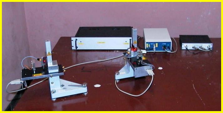
Nel corso del 2003 sono stati completamente riattivati i due sismografi Wood-Anderson in dotazione alla stazione sismografica di Trieste operanti dal 1972 fino al 1987. L'originale sorgente luminosa, costituita da una lampadina ad incandescenza, è stata sostituita da un laser a luce rossa visibile e la carta fotosensibile da un "position sensing detector" (PSD). Il PSD è un dispositivo semiconduttore che fornisce in uscita una tensione proporzionale alla posizione del punto luminoso sulla sua superficie. E' quindi un trasduttore analogico. La sostituzione del vecchio sistema di registrazione è quindi diretta ed immediata. Dopo essere stati filtrati (anti alias) i segnali vengono convertiti in digitale e memorizzati su PC. Nel corso del 2004 ai due strumenti è stato affiancato un sismometro broadband tre componenti con lo scopo di verificarne l'ingrandimento statico.The original Wood-Anderson instruments in use from 1972 until 1987 in the seismological Trieste department were again put into operation during 2003 was modernized passing the recording system from the analogic to the digital format. The original light source, a bulb lamp, was replaced by a red visible laser source and the photosensitive paper by a "position sensing detector" (PSD). The PSD is a semiconductor device giving as output a voltage proportional to the spot light position on its surface. Then it is an alogue device. After antialiasing filtering, the data are converted in digital format and recorded in a hard disk. In 2004 a broadband seismometer was placed side by side to the instruments to check their static magnification.
LA NUOVA LEVA
OTTICATHE NEW OPTICAL
LEVERAGE 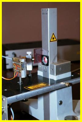
Ai
due strumenti originali è stato tolto il secondo specchio
cilindrico e le due lenti poste nella finestra ottica. Togliendo
lo specchio cilindrico con il suo supporto si è ottenuta una
piccola finestra laterale attraverso la quale si fa passare il
raggio laser. Così facendo restano inalterati gli angoli
operativi dello specchio mobile e quindi le procedure di
taratura dell'apparecchiatura. L'unica differenza con
l'originale è che la leva ottica originale, subendo i raggi
luminosi due riflessioni, era moltiplicata per quattro e la
nuova leva, subendo il raggio una sola riflessione, viene invece
moltiplicata per due.The
second cylindrical mirror and the two lenses placed in the
optical window were removed from the two original instruments.
The removal of the cylindrical mirror with its support has
produced a small side window through which the laser ray hits
the mirror. In this way, operating angles of the mobile mirror
and consequently the equipment calibration remain
unchanged. Changing the numbers of the light reflections,
now only one, effects the optical lever to change from four time
the fisical length of the light path to only two times.
Il sensore utilizzato è l' 1L20 della Sitek. E' un sensore monodimensionale con un'area attiva di 20x3 mm sensibile alle radiazioni visibili. La linearità tipica è dello 0.1% entro l'80% della lunghezza della superficie utile. La risoluzione può arrivare ad essere migliore di una parte su un milione e dipende dalle soluzioni ottiche, elettriche e meccaniche adottate. Ha due anodi (Y1 e Y2) ed un catodo (bias). E' sensibile alla posizione del centroide dello spot luminoso incidente sulla sua superficie attiva. La posizione Y del centroide viene calcolata con:The sensor used is the 1L20 of the Sitek. It is a 1D sensor with an active area of 20x3 mm sensitive to visible radiation. The typical linearity is 0.1% within the 80% of the length of the surface. The resolution may be better than one part per million and depends on the optical, electrical and mechanical solutions adopted. It has two anodes (Y1 and Y2) and a cathode (bias). It's sensitive to the centroid position of the spot light incident on its active surface. The centroid position along the Y is calculated by:
Nel 1996 l'INGV aveva realizzato un sistema simile ma basato su di un sensore CCD che, essendo essenzialmente un trasduttore digitale, richiede elaborazioni aggiuntive rispetto a quelle richieste dal PSD, sia per l'interpolazione della posizione del segnale ottico sia per l'attuazione di filtri anti-alias ( Romeo, 1996)In 1996 the INGV realized a similar system, based on a CCD sensor. The CCD is essentially a digital transducer with additional processing for the interpolation of the optical signal position and more complexity for implementing anti-alias filters (Romeo, 1996) compared to the PSD..
ACQUISIZIONE DEI
SEGNALI REGISTRATI DAI DUE TS-220RECORDING
Al segnale in uscita viene applicato un filtro anti alias a 6 poli con 40 Hz di frequenza di taglio. L'acquisitore è a 16 bit con frequenza di campionamento di 100 Hz. Il salvataggio dei dati avviene tramite trigger STA/LTA. Vengono memorizzati solo gli eventi rilevati dal trigger. La temporizzazione è realizzata tramite un sistema GPS.At the output signal is applied a 6-poles anti alias filter with a 40 Hz frequency cutting. The 16-bit recorder has a 100 Hz sample rate. Data storing is performed via trigger STA / LTA and it is possible a continuous recording. Only triggered data are currently stored. Timing is achieved through a GPS system.
I due strumenti Lhener-Griffith TS-220 sono orientati N-S ed E-O. Sono stati smontati, puliti e completamente ricalibrati.
Nella tabella seguente sono riportate le caratteristiche delle due componenti.The two instruments Lhener Griffith-TS-220 are oriented NS and EW. They were disassembled, cleaned and completely recalibrated. The following table shows the two components characteristics.
| componenteOrientation | periodo (s)Period (s) | smorzamentoDamping |
| N-S | 0.792 | 0.787 |
| E-O | 0.796 | 0.818 |
Originariamente quando l'indice posto sulla base degli strumenti era su uno dei riferimenti laterali riportati sulla base stessa si doveva leggere sulla carta uno spostamento di 50 mm. Ora basta dividere 50 mm per il numero di counts risultanti per stabilire la sensibilità ed impostarla nel codice di acquisizione dati. In uscita avremo direttamente l'ampiezza in mm delle tracce equivalente a quella che si sarebbe avuta sulla carta fotosensibile.Originally, when the index placed on the basis of the instruments was on one of the marks you had to read the displacement of 50 mm on the paper. Now you need just to divide 50 mm for the resulting number of counts to determine the sensitivity of the instruments and set it in the data acquisition code. In this way in output we will have directly the width in mm of the tracks, equivalent to that which we would have on the photographic paper.
INGRANDIMENTI
STATICISTATIC
MAGNIFICATION
In letteratura si trovano lavori che hanno tentato di stabilire l'ingrandimento statico del TS-220 dalle sue caratteristiche meccaniche (Uhrhammer et al., 1990) . Occorre comunque considerare che la costruzione meccanica e la filosofia generale di applicazione dello strumento rendono molto ardua un' analisi di questo tipo. La valutazione dell'ingrandimento statico dipende soprattutto dall'esatta collocazione del filo di sospensione (diametro 0.02 mm) su di un cilindretto di 2 mm di diametro sul quale è fissato lo specchio mobile. Il filo deve essere esattamente a 22.5° rispetto al piano dello specchio(Anderson et al.,
1925). In fase di calibrazione l'esatto valore di quest'angolo, difficilmente verificabile a causa delle dimensioni in gioco, è fondamentale nella valutazione della componente dell'accelerazione di gravità applicata. Un errore di, per esempio, 0.1 mm nel fissaggio del filo equivarrebbe ad un errore nell'angolo di circa 6° e ad un errore sulla valutazione dell'ingrandimento di circa 140. Altra causa di errore è la difficoltà nel livellare la base dello strumento in modo da disporre lo specchio mobile a 22.5° rispetto alla superficie esterna del sismometro. Tutto questo porta ad un notevole spread di valori quando si vanno a testare diversi strumenti: Gutenberg nel 1957 ottenne, utilizzando un tavolo vibrante, un valore di 2800 +/- 500. Il Wood-Anderson reale evita la gestione di questi problemi: lo strumento viene tarato per avere una traccia ampia 50 mm quando l'indice della base è posto su uno dei riferimenti laterali. Il problema si pone quando si vuole simulare lo strumento su registrazioni effettuate da altri sismometri (es.: broad-band).In literature there are works that have attempted to establish the static magnification of TS-220 from its mechanical characteristics
(Uhrhammer et al., 1990). However, the construction mechanics and the general philosophy of the instrument application make it very difficult. The static magnification assessment depends mainly on the exact location of a cylinder of 2 mm in diameter, where the mobile mirror is attached, suspended on a wire of 0.02 mm in diameter. The wire must have exactly an angle of 22.5° with the plan of the mirror (Anderson et al., 1925). The correct calibration of this angle, really difficultly verificable because of the sizes involved, is crucial in assessing the gravity acceleration component applied. An error, for example, of 0.1 mm in the wire fixing procedure means an angle error of about 6° and a magnification evaluation error of about 140. Another cause of errors is the difficulty in leveling the instrument base to put the mobile mirror mobile at a 22.5° angle with the outer surface of the seismometer. All these problems lead to a significant spread of values when different instruments must be tested : in 1957 Gutenberg obtained, using a vibrating table, a value of 2800 +/- 500. The Wood-Anderson usage avoids the management of these problems: the instrument is calibrated to have a track of 50 mm when the base index is placed on one of the side references. Problems arise simulating the instrument with recordings made by other seismometers (eg.: broadband).
Per l'analisi degli ingrandimenti statici reali dei due wood-anderson, nel corso del 2004 è stato affiancato ad essi un sismografo broadband Guralp 40-T con periodo massimo di 60 s. L'acquisizione, in continua, avviene tramite digitalizzatore Guralp 24 bit integrato nello strumento. Sui 1252 eventi registrati fino al dicembre 2013 è stato effettuato un confronto tra le ampiezze registrate dagli strumenti originali e quelle ottenute simulandole sui segnali broadband. L'ingrandimento statico G è definito come:For checking the real static magnification of the two Wood-Anderson instruments, during 2004, a Guralp 40-T broadband seismometer with period extended to 60 s was placed near our instruments, acquisition accomplished by an embedded 24 digits digitizer. Until 2013, 1252 events have been recorded and Sandron et al. (2015) compared the amplitude of the real wood-anderson instruments with that ones obtained by their simulation on broadband. The static magnification G is:
A è l'ampiezza di picco della traccia sul sismogramma e a è lo spostamento del terreno. Quindi se Gw e Gb rispettivamente gli ingrandimenti del
wood-anderson e della sua simulazione sul broadband e Aw
e Ab le rispettive ampiezze, ponendo Gb uguale a 2800:A is the trace peak amplitude and a is the ground motion. If Gw and Gb
are respectivetly the magnification of wood-anderson and its simulation over broadband signal and Aw and
Ab their peak amplitude, setting Gb
= 2800 will be:
Gw = 2800 Aw/Ab
Nella seguente figura in a e b si possono vedere i risultati ottenuti tramite media pesata su una finestra mobile di 50 eventi. Analizzando l'andamento delle funzioni inaspettatamente si nota che la risposta
risulta non essere lineare ma seguire una sorta di legge
di potenza funzione dell'ampiezza dei segnali (Sandron et al., 2015). Dal grafico N-S si può constatare che l'ingrandimento statico risulta avvicinarsi a 2800 per ampiezze inferiori a 0,05 mm, e tendere asintoticamente a 2080 per le ampiezze superiori a 1 mm mentre per la componente E-W la curva risulta spostata verso l'alto di circa 200, tendente quindi a 3000 per le basse ampiezze e 2280 per le ampiezze maggiori. I risultati riguardanti la componente N-S sono più affidabili di quella E-W. La stima dell'ingrandimento di quest'ultima potrebbe non essere corretta poiché lo specchietto, che era parzialmente staccato dalla massa, è stato riattaccato cercando di conservare i 22,5° (vedi sopra) cosa per nulla agevole viste le dimensioni in gioco.The following figures show the results achieved by weighted average over a 50 events sliding window. We can see that the
response is not linear but follows a power law, function of the
amplitude of the trace. In the N-S graph the static magnification asympototically approaches 2800 for lower amplitudes and 2080 for the higher ones. In the E-W graph the response is shifted upward of about 200. Results of the N-S component are more reliable because in the E-W the mirror was partially detached from the wire and it was repaired by us trying to save the 22.5° (see above).
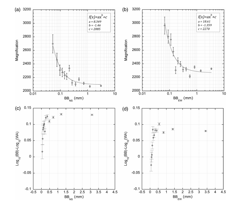
Fig. 1 - Ingrandimenti statici e magnitudo
corrispondenti dei wood-anderson reali in funzione di quelli
simulati su registrazioni broadband delle componenti nord-sud
(a, c) e est-ovest (b, d). Da Sandron et al,
2015Fig. 1 - Static magnification of the real wood-anderson
instruments and magnitude difference versus their amplitude
(simulated) on broadband data. N-S component on left (a, c) and
on right the E-W (b, d). See Sandron et al,
2015.
Alla luce di quanto emerso dalla comparazione delle ampiezze dei segnali reali WA con quelle dei segnali simulati dalle registrazioni broadband appare evidente che nell'utilizzo degli strumenti originali si ha un'incertezza nel calcolo della magnitudo pari a circa +/- 0.13 gradi Richter dovuta alla dipendenza dell'ingrandimento statico dall' ampiezza del segnale. Questo ovviamente non si verifica simulando gli strumenti sulle registrazioni broadband, in questo caso però resta incerta e del tutto arbitraria la scelta dell'ingrandimento statico da inserire nella funzione di trasferimento.Looking at our results about the comparison of real Wood-Anderson data with their simulation over broadband signals, magnitudes calculated by the original instruments have an uncertainty of about Richter degrees dues to the dipendence of their static magnification on amplitude of the peak traces. Obvioulsy such a behavior does not appear in the simulation over broadband data, but in this case the uncertainty of which magnification (2800 or 2080) to use remains.
Gli strumenti sono
installati presso la sede dell'OGS in Borgo Grotta Gigante
(Trieste) (coord: 45.709° N, 13.764° E, alt.: 330 slm).The two instruments are
located at the OGS in Borgo Grotta Gigante (Trieste) (coord:
45.709° N, 13.764° E, alt.: 330 m).
La componente N-S è attiva dal
31/10/2002 e quella E-O dal 13/12/2002.
I seguenti
links danno accesso ai cataloghi dei terremoti registrati dai wood-anderson e dal broadband posto loro accanto 2004-2013 2014 2015.
Magnitudo dei terremoti registrati della sequenza sismica successiva alla scossa principale del terremoto di Amatrice (RI) del 24/8/2016 link
Sono riportate sia le magnitudo locali calcolate con i wood-anderson (MAW) sia quelle ottenute simulando gli strumenti sul broadband accanto ad essi con ingrandimento 2800 (ML2800).The
N-S component is working from 31/10/2002 and the E-W one from
13/12/2002. The broadband seismometer is operative from October
2004. In the following links the catalogues of the
earthquakes recorded through them 2004-2013
2014 2015.
The following link
shows the magnitude of the earthquakes after the 08/24/2016 Amatrice mainshock. Data recorded by the real woodanderson instruments (MAW column) and simulated on the broadband recordings with magnification 2800 (ML2800 column), are reported. link
RIFERIMENTI BIBLIOGRAFICIREFERENCES
- Anderson J. A. and Wood H. O., 1925: Description and Theory of the Torsion Seismometer; BSSA, vol. XV.
- Finetti L., Morelli C., 1972: Earthquake magnitude determination for Trieste WWSS station; Bollettino di Geofisica Teorica ed Applicata, Vol. XIV, n. 53-54.
- Manuale del sismometro Lehner-Griffith mod. TS-220.
- Richter C. F., 1935: An Instrumental Earthquake Magnitude Scale; BSSA, 25 pp. 1-32.
- Richter C. F., 1958: Elementary Seismology; W. H. Freeman and Company; S. Francisco.
- Uhrhammer R. A. and Collins E. R., 1990: Synthesis of Wood-Anderson Seismograms From Broadband Digital Records; BSSA, vol. 80, pp. 702-716.
- Uhrhammer R. A., Loper S. J. and Romanowicz B., 1996: Determination of Local Magnitude Using BDSN Broadband Records; BSSA, Vol. 86, n. 5, pp. 1314-1330.
- Romeo G., 1996: Wood
Anderson digitale; rapporto interno INGV.
-
Sandron D., Gentile G. F., Gentili S., Saraò
A., Rebez A., Slejko D., 2015:
The Wood-Anderson of Trieste (Northeast
Italy); One of the Last Operating Torsion Seismometers;
Seismological Research Letters, vol. 86.